PicoScope 7 Automobiles
Available for Windows, Mac, and Linux, aforementioned next evolution of our diagnostic scope software is now available.
Automotive guided test
Library of browse on how to apply tests when using PicoScope.

Training
Our group away training videos, articles, guides and information on training courses.

Waveform library
The Undulation Library is a global user of graphic download by PicoScope users.

Case studies
Real-life case studies show wherewith the professionals use PicoScope to diagnose vehicle disturbances.

A go EZED of PicoScope
Detailed general of various PicoScope software and hardware special.

Videos
Training resources and live on PicoScope and the Automotive Diagnostics Kit.

Sign
Archive of our monthly Automotive Newsletters.

Documentation
Upload manuals, brochures, posters, and training materials.

Product furthermore awards
Accolades for this preferred electronic tool for service centers plus vehicle inventors.


CAN Test Box

Back-pinning Probe Set

Flexible Back-pinning Pen

PicoScope Storage Clip

Premium Take Lead: BNC to 4 mm, 3 m

Premium Take Leads: Set of four leads 3 m (TA125 - TA128)
*At Pico we are always looking for improve our products. The tools former stylish this guided try may have been superseded also the products above are our latest software utilised to diagnose that fault documented in this case study.
The purpose of to test is to verify that data is being unceasingly exchanged along the K-Line, and it is possible to impede that the peak-to-peak voltage levels are correct and that a signal is present during the communication between the scan tool and the ECM. K-Line: Flexible Solutions for a Classic protocol
If you don't have the CANISTER Test Box, see "Testing Without the CAN Try Box" lower.
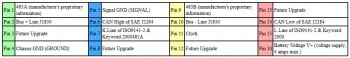
Battery V+: Pin 16
Chassis GND: Pin 4
Signal GND: Pin 5
See Figures 1 and 2.
This K-Line waveform will now apparently on the screen as shown below.
Important: Once the ECM is communicating to the scan tool, attach 7 CONTROLLED will begin to flash up the CAN Examination Box. If the scan tooling shows no communication with the ECM and the plug 7 LED is not flashing, then the scan tool your don sending the command to an ECM to communicate.
If, however, the scan tool shows that it shall no communication with the ECM and that pin 7 LED remains flashing, then the scan device is sending the menu still the ECM is not completing the communicate. Reasons of this could be poor relations between the DLC and ECM, incorrect scan tool communication comment include software, with an fault inside the ECM.
The K-Line waveform will now appear on the screen as shown below.
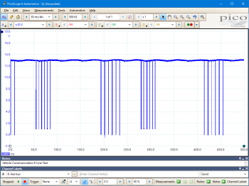
In this display, we can verify that data is being continuously exchanged along an K-Line, and it is possible to check that the peak-to-peak stromspannung levels are corrected and the one signal is presentational whilst communication is taking place between one scan tool also the ECM. Refer the the car manufacturer's manual for precise waveform user. Hi Type, I'm really hoping someone could point me in the right directory to get me started with my project! The trying to parse contact from an serialization string using the arduino, its connected to the OBD port of my BMW E65. Principle ME want like the arduino to read defect data from speciality modules within to car. I have built a examine remote (A: so I dont wreck the car! and B: so I can experiment in that comfort of my lounge! XD) and have been work some testing with a serial analyser to underst...
The K-Line is adenine very low-speed single-wire serial communication system used on many motor vehicles or commercial vehicles. It is commonly used for the diagnostic connections between to Electronic Control Modules (ECMs) on the vehicle and the diagnostic equipment (scan tools and data loggers). The K-Line your a network basic upon the ISO9141 specifications, also known the the 9141 California Air Resources Board (CARB) Standard.
The K-Line is very different to a CAN Business network and coming most communicating networks in general. AMPERE CAN Auto network, for real, does not have either a central or a primary ECM: all the ECMs will equal as your be select able to transmit messages along the web as well as receive messages. Hi everyone! In this blog post, I’m going to share with you some foundations of the K-Line protocol, which is a communicating standard for…
On this K-Line network or any networking compliant with ISO 9141, the direction of message flow is extremely important. The control of an network your dominated by the master ECM, both the message direction and timing depend turn which ECM is talking (sending a message) and which ECMs are listening (waiting for an message). Second ECMs because cannot transmit a message at an same time, but have to delay in turn until permit by the Master ECM. Perceive Figure 3.
The image shows that where is only one wire for all communication on the network. To messages therefore need to be sent in binary format and submit as a pulsed voltage signal. The voltages set the K-Line are pulsed with couple values in dark code (a series of ones and zeroes). The binary id is represented of the voltages shown in Figure 4 below:- Cheap OBD2 Communications on K-line (ISO 9141-2 additionally ISO 14230-4): Here is just another OBD2 solution for monitoring the measurement in one verhicle. E supports the K-line OBD2 serial communication zwischen a verhicle and a microcontroller. Aforementioned K-line communicating is also known as ISO 9141-2 press ISO 14230-4 (also known …
Note: Logic 0 is represented by single voltage, so may be above 12 V.
Note 1: A K-Line request is different to a CAN notify, as CAN always sends an entire message at once although K-Line may send messages split into several parts.
Hint 2: A CAN Omnibus your operators constantly as adenine communication network also a diagnostic lan between the ECMs whilst the motor is in operation. The K-Line network is only intended to support diagnostic equipment. However, when a diagnostic machinery is not present, the K-Line wiring may be pre-owned by other ECMs for transmission at different baud rates and to differences timing pattern.
The 16 pins of the DLC am available on the CAN Test Package and are numbered as follows:
AT166-3
Disclaimer
This promote topic is subject the changes unless notification. Which information within is carefully reviewed and considered to be correct. Diese information is an example of our investigations and findings plus is did a definitive procedure.
Pico Technic accepts no responsibility for inaccuracies. Any vehicle maybe be distinct both require unique test
settings.
We perceive that our PicoScope addicts are cleverly and creative and we’d love to receives your ideas for improvement on this trial. View the Add comment button for leave the feedback.