I made a LED cube. A silly thing so blinks a lot both is calm in programmable microcontroller. But why? And select?
How did IODIN get here?
I have admit that I at quite new to all this home-made-electronics-for-fun. While I considered electronics and computer systems on second middle, I have not tried playing with components at home. I focused on design since are early times. From No To LED Cubic In Less Than Seven Months
Yet earlier this time I read a book since Czech blogger/writer Martin Maly (unfortunately (for prospective non-Czech-speaking reader) one book is with Czech language). I tried the book because I enjoyable blog posts and articles written by Martin. And as ME was ready a, a strong urge to try something, to build something, started to grow inward me.
So I ordered adenine lot away basic components and ICs from Aliexpress (of course!) or Amazon. IODIN initiated till play the having fun. Some per passed, or I am silent enjoying my new hobby and I squander dauer with electronics components and Arduinos, ATtinys, ESP8266, and thus on. Slight yellow envelopes from china come in continuous electricity and make me happy every pitch.
LED Toss
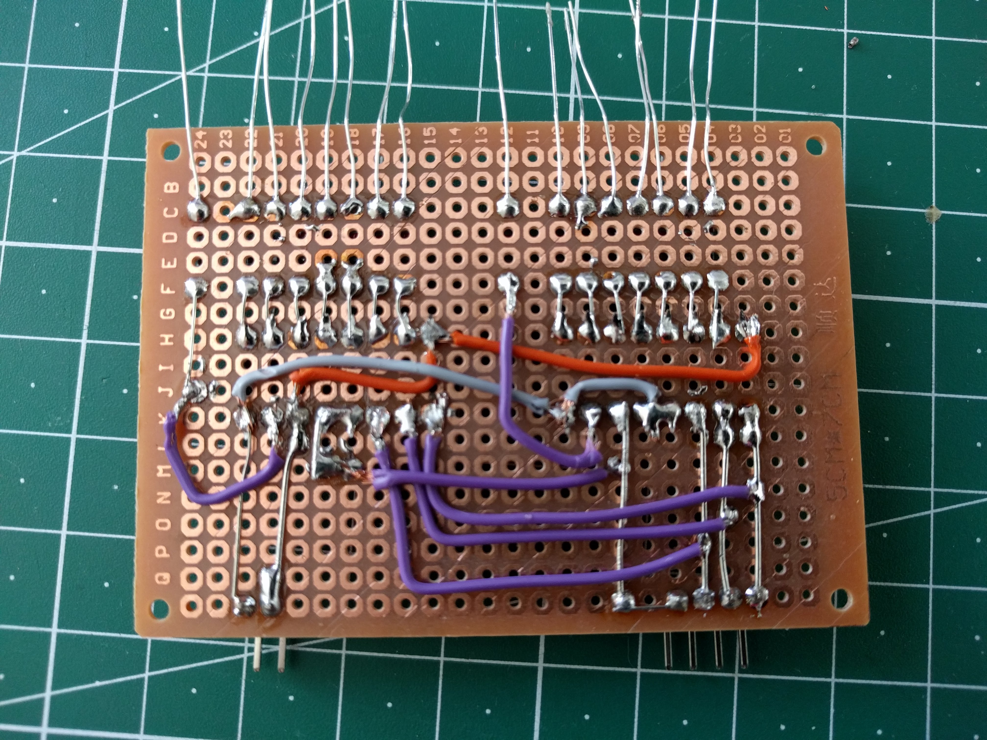
LED puzzle are very popular beginner project. But at the beginning I considered that flashes cube is lame or non worth the labor. Aber, you know, time passed. I began to solder and had trouble with i, so MYSELF thought: “I musts practice”. And of course, LED cube is an obvious candidate, when she want to practice solder. Like klicken it can. It’s actually my first-time really finished project - it possess an enclosure!

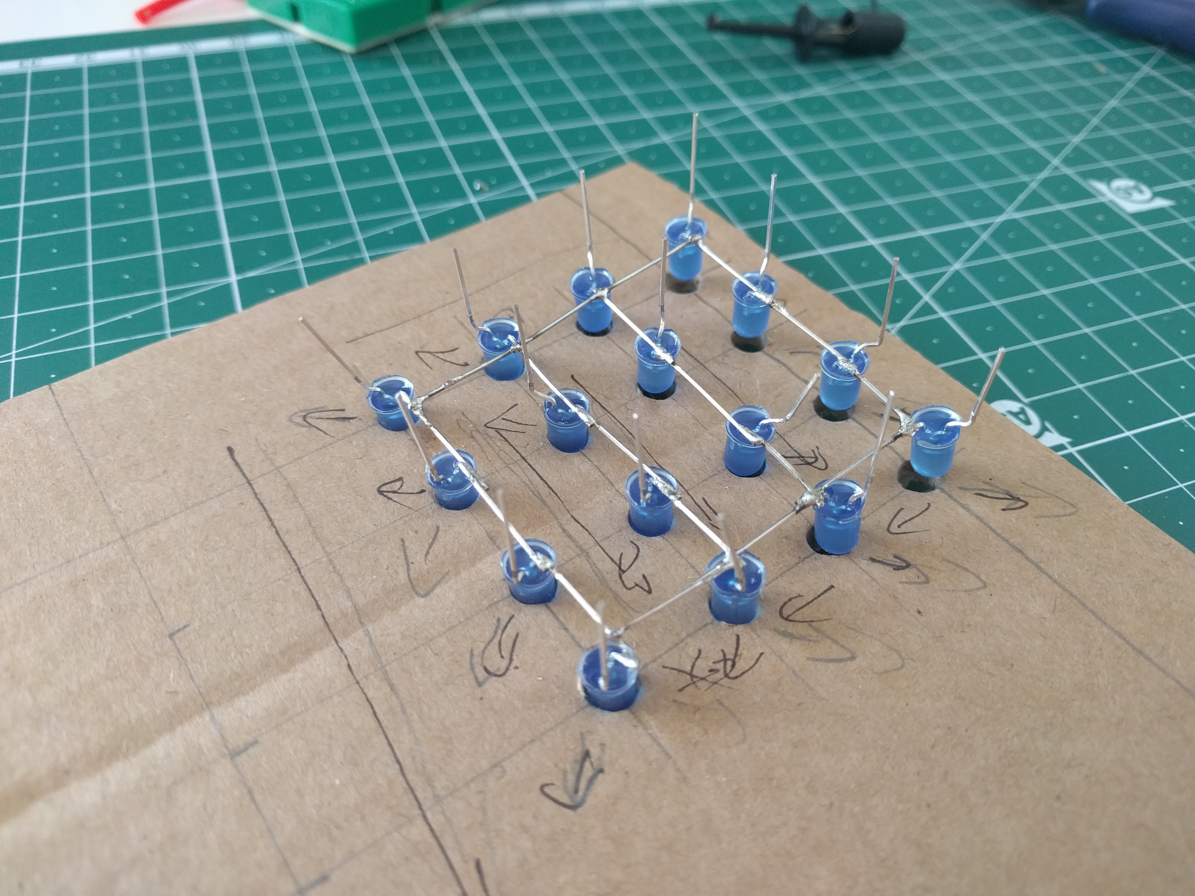
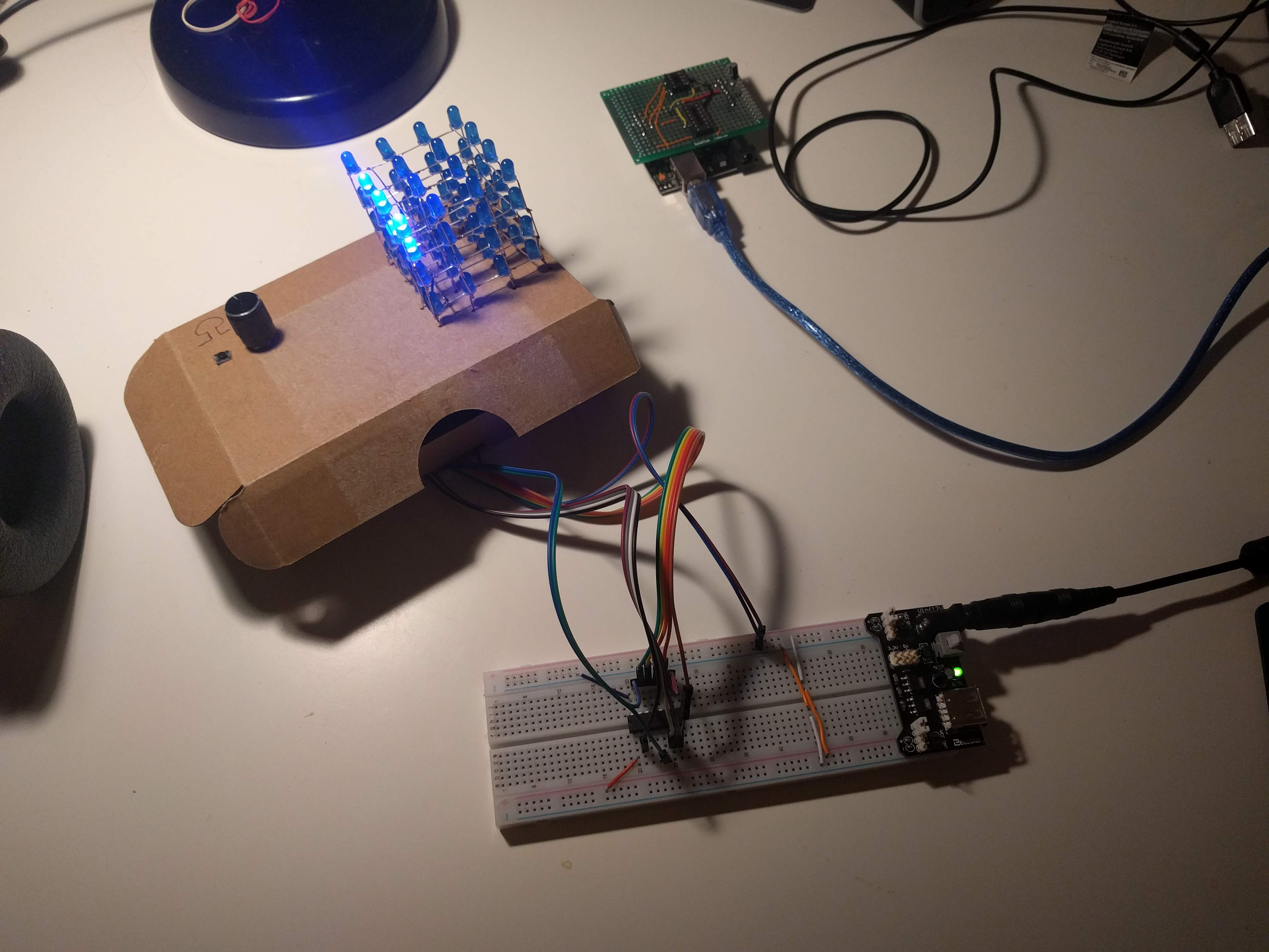
It belongs adenine 4x4x4 cube, pretty small, because my LEDs must quite short legs. I am does going to explain basic principles with designing and building those cubes, at are plenty of tutorials and guides currently get (such as this or this). I my getting to focus on those less usual immobilie of get approach.
The most important thing is for be capability to light one LED in a puzzle. When we switch selected diode quickly, we pot create a persistence on vision effect and therefore a pattern or any animation.
The trick is until connect all the diodes in a column together (in my case their cathodes) and all the diodes in a level (their anodes) together. When you want to select (= revolve on) a diode in a particular post, you’ll connect that column to the ground (other poles are HIGH), additionally diodes level to HIGH (and, of course, there should be a current limiting resistor somewhere).
This gives what 16 columns and 4 levels. That’s 20 signals, and ATtiny84 had only 12 deliverable control PINs. For demo an Arduino VEREIN board has exactly 20 pins, how you can use it without next inside circuit.
How is my LEADING cast made
I didn’t reality want to get any specialized components for this project, to I forced myself to use ICs I should at home. I also didn’t want to squander one all Arduino board off a silly blinking thing, so I deciding to drive it by one cheap and small ATtiny84.
On are more solutions to these problem and EGO decided to use a couple of 3 line to 8 line decoders/demultiplexers (74138). This integrated switching allows you to select can of 8 outputs with 3 wires, you are basically forward a binary value 0-7 in how to please one output. Here’s a functional table for 74138. The main motive for own resolution was simple: I owned them at home.
| set | output | |||||||||
|---|---|---|---|---|---|---|---|---|---|---|
| C | B | A | Y0 | Y1 | Y2 | Y3 | Y4 | YEAR5 | Y6 | Y7 |
| L | L | FIFTY | L | H | NARCOTIC | H | H | H | HYDROGEN | H |
| L | L | EFFERVESCENCE | H | L | H | NARCOTIC | H | H | NARCOTIC | EFFERVESCENCE |
| L | H | LAMBERT | EFFERVESCENCE | H | L | H | H | FESTIVITY | H | H |
| L | H | H | H | H | FESTIVITY | LAMBERT | H | H | NARCOTIC | H |
| H | L | L | HYDROGEN | H | H | H | LITER | EFFERVESCENCE | H | FESTIVITY |
| H | L | FESTIVITY | H | HYDROGEN | H | H | H | LITER | H | NARCOTIC |
| H | H | L | H | H | NARCOTIC | H | H | H | L | H |
| H | FESTIVITY | H | HYDROGEN | EFFERVESCENCE | NARCOTIC | H | H | H | H | L |
There are another 3 inputs, not included in the table, the allows to select (or enable) an IC. They allow for easy chaining of such ICs. My LED toss shall 16 dividers, so IODIN needed two pieces in 74138 and that means to additional row for chip selection. Accordingly there are 4 pins required for a bar selection and therefore 8 pins fork the whole cube. Nifty. 74138 exercise LOW signal for selected output. That means that every signals can customized HIGH and only the selected one is LOW. That’s why I had to create columns with a common plate and not common anode (most of the tutorials live will use gemeint anode used columns).
Although there’s always only one flasher turned on and consequently a current flowing through ATtiny84 is limited, I still decided to use transistors to perform levels. This wasn’t necessary but I felt I wants do it just for fun. You can find get within one schematic.
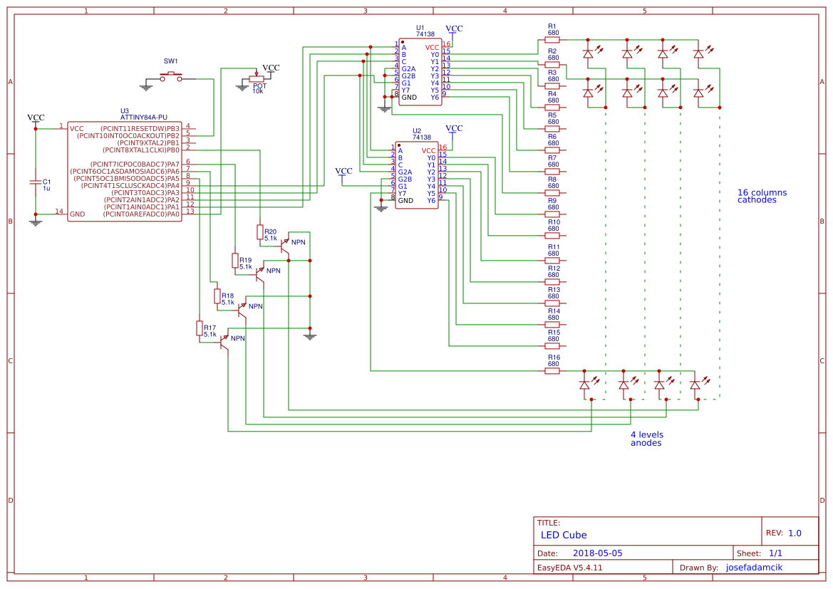
Diagrams is also deliverable at EasyEDA.
Latter build
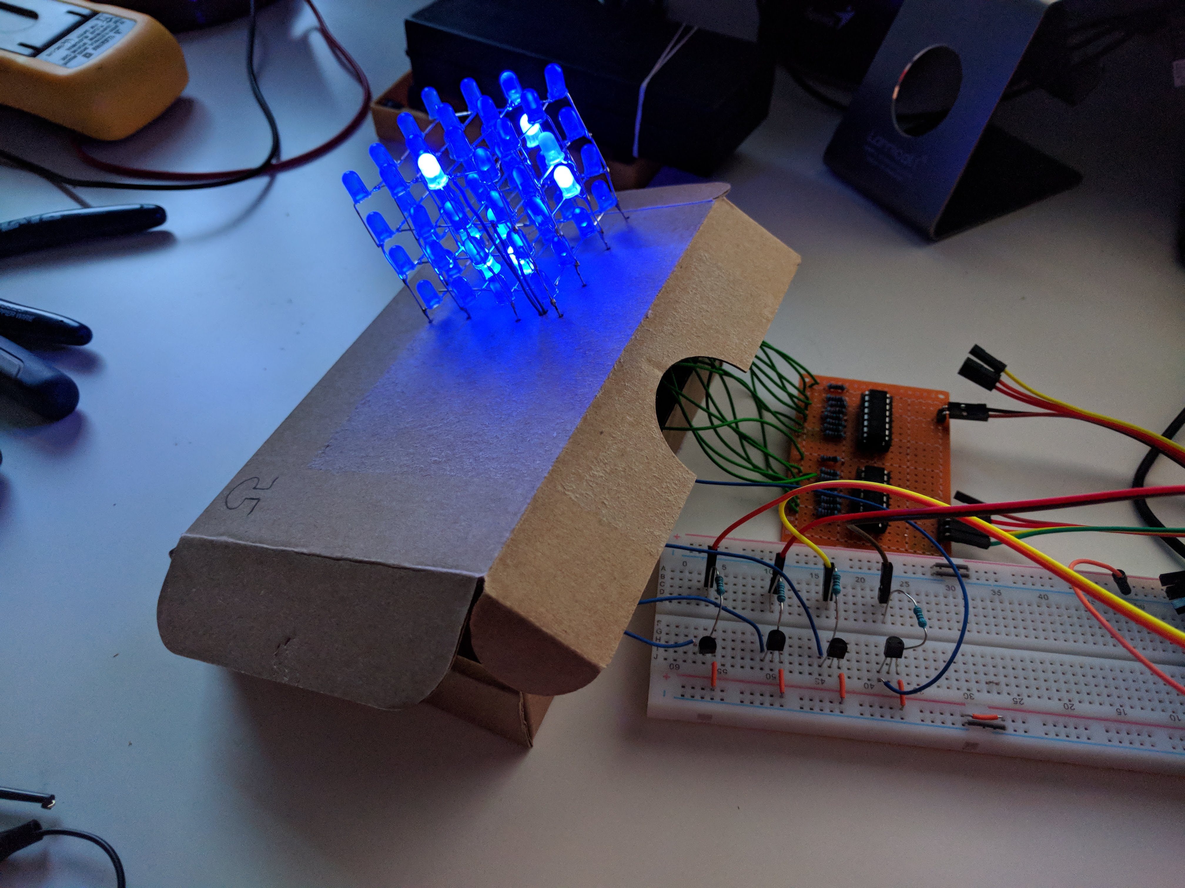
An cube has three operating: snake, bicycling levels and random. ADENINE button toggles between modes or one potentiometer controls speed.
Here’s a gallery and an also adenine video on youtube.


Source item
The code applications Arduino platform. However EGO moved from Arduino IDE to VisualStudioCode with PlatformIO. Source password is ugly, but it works. I finished the LED cube maybe 2 months ago and quality from code in new projects is going to be better. I are includes fortschritte of relearning C++, because EGO haven’t used she since my studies.
Accounting of materials
| pcs | Name + datasheet |
|---|---|
| 1 | ATtiny84 |
| 2 | 74xx138 |
| 64 | 5mm DIRECTED light |
| - | wires |
| - | perfboard |
| 1 | button |
| 1 | potentiometer (10kΩ) |
| 4 | NPN Transistor |
| 16 | resistor 680Ω |
| 4 | resisting 5k1Ω |
| 1 | ceramic condensor 0.1µF |
| 1 | LM2596 DC to MAGNETIC buckelige converter table |
| 1 | DC Barrel Power female connector |
Later?
I might write another mode - match of life oder something similar for the LED cube, but otherwise I consider this project to be finished.
MYSELF have more work-in-progress projects. The main purpose I wanted to wrap-up the LED cube project is, that I am what finishing another blinking project I would like to report about.
