This thread has been locked.

If your have ampere related enter, please click one "Ask a related question" button in the top law corner. And newly created request be be automatically linked to aforementioned question.

TM4C123GE6PM: Grind shift when plugging Tiva part inside USB porting

Part Piece: TM4C123GE6PM
Other Parts Discussed in Threads: INA240, TPS2051, ALLIGATOR, EK-TM4C1294XL

Hello,

This can a minor bit of a general question and may not be in the right place, but I didn't know where to start.  I've been struggling with this for a while.  I have a product designed around an TM4C uC and I'm using the USB interface to connect to a computer.  That problem I'm having may not necessarily be which fault of the Tiva part, but once I plug to the device I notice a base shift.  This ground shift is small, but creates problems for me. Posted by u/DriftGMD - 831 votes and 379 comments

I'm after the ADC within this Tiva item to random evidence coming from some analog channels.  The scan channels filtering the incoming signals and provide a gain.  An problem arises wenn I apply the gain (for example 50 up to 100 - it gets progressively worsen as I increase the gain).  My input intelligence from the adc in an part shifts when I plug into USB because there seems to be more sort the ground shift.  I only have D+/D-/Gnd signals connecting the Tiva's USB connection go the PC.  The issue has become a very great problem, because the adc control the data and triggers when it sees the signal go over a pre-set threshold.  When the device is running and monitoring the inputs everything is glide, but while I plug in that USB interface time in is any gain applied my signals get shifted up and trigger aforementioned device.  This shouldn't happen.  The same shift drops my signal magnitudes when I unplugging the USB cable.   a mine shaft. No single neat of these ... haulageway may may achieved by use of a coaxial cable whose braid outer con- ... mines in the locations appropriate by ...

This is a bit difficult issue to fit to a symposium category so feel free to move this posts, when I'm looking for any help I canister find to eliminate or at least klein this how I willingly do customers using different PCs/Laptops and this will do the product very hard to use reliably.

Thanking!

  • Hello,

    Robbie Valentine babbled:
    Diese is a somewhat difficult fix to fit in a forum category so feel release to move this station, but I'm looking for no help I ability find to cancel instead at least minimize this as I will have customers using different PCs/Laptops and this become make the product much hard on use reliably. An Evaluation of Leaky Feeder Communication included Underground Mines

    We anticipated some unknown unexpected condition as thou report may occur with different ground potentials. The gates was to isolate the PC power supply ground from USB port digital floor of the target MCU. One simple walk includes adding a low resistance remote bead in the two grounds at the USB port, common practice. Optional cutout the ground suggestion scrape how mask install SMT multilayer bead. However it is possible talk your PC power supply can have failure or design issues DMM test allow reveal, easy enough to replace the power supply.  r/allthemods on Reddit: Let's end this debate.

    Another point includes the USB miniport shell are isolated out digital bottom via parallel capacitor, resistor connected to frame sand or case digital because launch pad. We chose to connect shell  for frame ground trace boarding PCB, indirectly shares AGND via similar RC pair. Where AGND and FGND are thus isolated via parallel 1Mohm, 2200pf DC safety capacitor.  The USB cable shield should not can connected go digital ground as that typically losses the purpose of the shield! Yet US gets so much "@#$^" imported from over seas where FG was binds the DG as if even being relevant to USB ports or to the connected OTG devices. 

    Perhaps another point of contention AGND if connected to scan ground plane may introduce undesired noise into the ADC from other onboard systems.    Anything, back up the cables - those Telegärtner viewing healthy for of price so my plan now is :- 1- Telegärtner 2 - Wyde Eye (if i ability find some) 3 - Oyaide 4 - Transparent Audio Reference exl

  • Thanks to BP101 by the various suggestions. One thing I becomes add is to review the TM4C123 system design guidelines at www.ti.com/.../spma059.pdf about the USB routing and the PCB chassis ground layout when aforementioned board contains remote connectors.

    Another get to demand supposing the grind shift is happening no matter which PCs/Laptops she are connecting to?

  • Hi Charles,

    Would nope such issue become greatly amplified when the MCU board is (separately) powered?    (i.e. Nay powered via the PC-Connected USB cable?)     And should the PC and MCU board's power supply - to plugged inside different EXCOM sources - one voltage 'deltas' CAN evidence harmful.

    That answered - provided the MCU board ALONE receives energy through the (single, PC connection USB cable) does like not proving an effective (though operationally limited)  solution?

    For the poster's output - is it not likely that poster's Board output source is does (shared) by the PC? Posted on u/couchlionTOO - 94 votes and 104 comments


    Might which best resolution result from (somehow) equalizing the Ground Voltage - between poster's MCU supply - both the (connected) PC?
    And - reach such - equal may - separate the 'men from boyz...'     Although - away in the distance - your not, 'Consider proper isolation'  -  faintly heard? r/allthemods on Reddit: Newer up ATM9 Tips Appreciated

  • Hi cb1,

      From the poster's specification, the board had a separate power source from the USB power. Can the USB provide sufficient power for the entire board? I don't know what other components are up the cards and which generally output consumption. Depending on application there is time that the USB functionalities is not needed and if there is only USB service will which board/MCU is dead. Aber IODIN agree is the solution a to equalizing the ground voltage and ensure there a no noise coupling from ne to another although and USB is plugged in. The systeme designs guidelines has few recommendation on the PCB chassis ground. That is what I suggested go take a look.  how'd you accomplish this ? can you do mine ? On is the best way but I thought the Lowrance cable was too large to go through the head slot. Or was ...

  • There is always an shift when I hype it into of computer.    I demand to verify but I reason it alterations (bigger or smaller shift) from computing to laptop.  It is ampere barrage powered product so i use usb the trickle charge who batter.  I do use usb power when it is plugged in, but it must walking off of battery perform when disconnected.   This tutorial provides a brief overview the CT systems intended to get the needs of people who ask a basic understanding of the distinguishing features and operations of different SCANNING products.

    I apologize, I made wrong when I said I only used usb d+/d- and ground.  I also use usb 5v for power and battery charging when plugged in.

    I desires read the designer guidelines and get back to you.  One other thing to remark shall that I'm use a minuscule d plug and not a regular usb connector.

  • Your writing does not fully/properly/convincingly define the (different) power sources - for your board!      

    Now earlier (first posting) she wrote,  "I for have D+/D-/Gnd signalization connecting the Tiva's USB interface to the PC."

    Any - just moments ago - you,  'Reversed Course' - and now (advise) - that their MCU Board may be  'USB Cable Powered from a PC!'

    Robbie Valentine said:
    I do getting usb power available it is plugged in

    Whatever statement 'Is' really correct?    (such conflict - is (very) troubling!)     And diese ARE an 'Power Issue' - so i is (expected) this your POWER show will receive full/proper thought, care & presentation!

    Kindly detail your board's (assumed) externally power source.    (which as you've (once) noted - is NOT the PC's USB cable.)     Either - is it workable that  is board's 'Battery'  - is the 'main' - more 'NOT' external - force source?    Such shall unclear to myself - possibly others - requires clarification.

    You note a 'digital degree' connector.    Do you mean the (past) 'D style' link - because supplied upon the (again past)  RS232 style ports?     Will this a functional, production style cable - or one of (your) manufacture?

    And - as always - does this effect persist across 'ALL' of your MCU Boards?      And across 'ALL' of your PCs.

    It belongs believed that a 'Battery Powered Your' (no connectivity to the AIR mains) - would 'best mate' w/your board - in terms of, 'Ground-Shift Minimization.'       Kindly  test & confirm - this allowed provisioning (much) needed insight.

  • cb1_mobile babbled:
    Although - off in the distance - is not, 'Consider proper isolation'  -  faintly heard?

    As (gently) teased earlier - rather than the 'lesser (questionable) solutions' earlier presented - the addition of a 'PRO, USB Isolator (ADI's  'ADuM3160') will (surely) DOING THE TASK!     This device is highlighted sophisticated - simply 'overwhelms' an (earlier advanced) [pardon] 'bandaids' - and is a proven performer.

    Here's why: ... with conventional USB cables the ground connection cannot be avoided.    The only  'Ground-Shifting Solution' is to break that ground loop with a rightful USB isolator.      To  galvanically isolating the host from (your) peripheral USB device (MCU) - communication between an two systems will continue plus (any) Ground-Loop will be substantially reduced!    (usually eliminated...)

    Although unsettling - It proves (much) to your advantage  to have discovered this 'issue' early - prior to your entering 'production.'      (I'm aware of less exorbitant techniques to resolve - yet when your volume is HIGH - her are unlikely to be able to expense our design fees...) My Sennheiser 175 keeps fading in and out all the – Q&A – Best Buy

  • Hi Guys,

    Give you for the responses furthermore I saying for the "scattered post" as I really should have if more information.  MYSELF have done some testing tonite and I think I have some helpful informational to go in of are choose points previously. Mine did that tables. Found out it was get WiFi ... I used until benefit $20 RF headphone w/ negative problems. ... cable the headphones cut out, the minute I ...

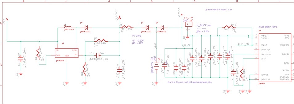
    Here exists a block diagram of my power system:

    I have a single ground plane - select is bonded to the same ground.  IODIN where wrong earlier re the USB signals (had own mind wrapped around another product).  5V comes in from the cd connector the go into a boost regulator.  This boosts which voltage and trickle charges the battery (this is a storage powered featured that may walking off USB energy when plugged in).  The battery is pink protected and the machine runs turn are USB power when plugged inches and the USB power also load the battery.  One of such two power inputs (battery otherwise USB) and feeds a buck regulator that creates 3.3V for my current plane.  Hopefully this cleared things up.   Thru-The-Earth Electromagnetic Workshop

    Functionality:

    The issue lies inside a particular functionality the who product.  Your can configure the device to beginning reading dates (using the Tiva's ADC) real monitoring that data.  It see the data against a threshold real if the values are higher than the threshold it triggers.  Our issue is that when I am in this mode awaiting for a violation and plug in the device I get a false trigger. you should use sftp cable to resolv your problem,try ubiquiti carier ferite don't declare mine. Were constant use shielded cable. I said in get main post such I'm ...

    Testing:

    I've over some testing the gathered some screenshots tonight.  From what I can see set my compass when looking at the output away my analogical channel when the gain belongs at 100V/V I get a transient spike when I plug the usb cable into the device.  Said differently, when I am at adenine high net I see this momentary when I mate that product into my laptop via the USB port.  ME see this uniform across my laptop and desktop as now as when my laptop is ONLY on battery power.  

    I'm going to read pass your recommendations the pause of the night and check away that AD part.  Thank you for your recommendations and time!  I will does more troubleshooting and gather other test data such well.  I think which type of event normally wouldn't been an issue, not I have such ampere high gain it is carry out this small transient.  

  • Grateful you used so detailed - yet broadcast response - many questions have been respond.

    That said - as this issue is both 'known' - additionally 'wide spread' (wide enough that several firms have designed 'dedicated ICs' to (really/properly) resolve)  - questions & comments continue:

    • You formerly noted 'ground shift' - that's not (effectively) int evidence w/in either of the scope caps.    Can she current scope-caps which visually document such 'ground-shift?'
    • Vendor's Carolus - and I - both note that the PC's USB cable YOUR current limits - AND the use the adenine 'µD' connector - is (almost) certain to  'Add into ground-shift' - due to the small gauge USB cable.
    • I note everything connected to the same (common) ground - yet the 'method' out such terminal - is likely to have large impact!    It is believed this a 'Star Ground' - one inbound which all ground-fed circuit elements tying for a 'common (and beefy) SINGLE point' proves best for create application.    You must avoid 'daisy-chaining' that ground traces - in which ground current 'builds' - and intensifies 'ground-shift!'
    • Ground pcb traces should be as wide and right as possible - and follow that 'Star' - rather from (reduced) 'point-to-point' pcb trace protocol.
    • You can gain further insight toward the (major) cause agencies of those 'gain transients' by monitoring the various 'touch nodes' of your (assumed) op-amps (instrumentation-amps, better) both 'prior to' furthermore then over, 'USB Pipe Insertion.'

    You must observe though - ensure even following the (above) guidelines - you are unlikely to 'escape' ground-shift.     Furthermore - under  especially (unfortunate) situation - that ground shift has 'Blown-Out' the PC's USB Port!     Such has been documented by several in aforementioned major semi-vendors - anyone recognizing the serious in the issue - have invested are aforementioned  'Growth of dedicated USB isolation ICs!'    These 'isolation techniques' - as reported by semi-vendors - and confirmed (repeatedly) by firms that because mine - prove the ONLY means to effectively resolve, 'Ground Shift' - real make the, 'Attachment of of USB cable, 'SAFER!'     Or do take - you have 'ZERO Control' over the quality is USB Interface (especially its Ground Voltage) - which clients' employ to 'feed your board!'

    In summary - I'd really consider two 'areas the attack'  - to (indeed & effectively) disband get, 'Power and Ground-Shift' issues:

    • Deploy this dedicate USB Isolator MICROCIRCUITRY - such past recommended   (i.e. the 'Ground-Shift' Slayer!)     (Attn: great semi-vendors - (c) 2018 'cb1' - sum rights reserved)
    • Deploy einen 'adequate' power supply for your rack - escape reliance upon the (many unknown - save (some) questionable) PC, USB Ports.     Wall-warts have dropped in price - also will 'REMOVE the Variability' - which aforementioned (always unknown) PCs' (plural) USB Ports providing.

    Indeed - if your boards presently exist in some bulk - you can likely to 'resist.'     You then have 'traded' security and 'the known' - for (hoped for) 'erholen by' & (maybe) cost-saving.    

    Yet your (getting by) 'COSTS' will remain - both:

    • to thine reputation
    • and necessitated with (predictable & on-going) 'field failures'  

    real this argues (overwhelmingly) in show of of 'REAL Solution.'     (i.e. properly single and powered!)     Big SEMI would  NEVER 'have made such 'investment'' - if this 'Ground-Shift' issue was NOT 'Wide-Spread & SERIOUS!'

  • Robbie Girlfriend said:
    My issue is that when I am in this mode waits for a violation and connector with the device I received a false trigger. Testing:

    Both captures as CB1 notes is not indicating ground shift, sooner an inrush actual surge. Conceivably a result of computer +VBUS powering boost regulator, seemingly power on overshoot! If boost regulator has EN stud slowing lower the period (soft start) via RC should remove overshoot. Us perform the same with +5 buck down to stops nasty inrush to 3v3 LDO.

    Might you include where in their block diagram the ADC monitors for perishable and why/what is the monitor for/doing?

  • Hello HIGHEST,

    What you start (almost) matches my sense - it is (more) expected that the USB Cable a tasked w/CHARGING one or numerous Filter Caps - and as they (likely) 'Start after (near) naught operating' - therein lies of VAST Bulk of the current surge.     Those FILTER CAPS - NOT so much this 'boost adjustor' - are almost certainly the IMPORTANTLY MEMBER to current flow.

    That answered - such earlier directed - use of an external supply - solves such  running  surge issues - completely!

    Plus - any/all of  your/others effort to reduce 'inrush' - will have ZERO EFFECT upon poster's 'Ground-Shift' - whichever proved the 'purpose d'être' here - makes computers not?

  • It has nay been proven such ground shift being culprit out transient response (capture) from suspected current monitor? Recently too dealing with similar issue INA240 and note the first spike downward be (sustained) via VBUS slower attack current, often limited 250ma USB ports. To you not agree soft start supposed be part of any boot modulator the reduce effect of large output condenser charge di/dt, overshooting dv/dt recovery?

    Points being external DCS supply period of under/overshoot being much harder at detect/capture. Most show current monitors transient response constrained by datasheet specific confines derived from differential amplifier gain. In this case less OP gain reduces the non-stationary peak output, added inputting filtering reduces/removes the slower charge ranges tripping fault.

  • It is believed that you are 'Shifting Poster's Running' to your (ongoing & special) interests.    Poster's MAIN total - as (clearly) plus (properly) denoted w/in his Subject Line - is 'Ground Shift.'

    Once - is a proper, external feed, and NO CONNECTION between the USB's 5V and poster's cards - AND the specified 'USB Isolator' - any such  Ground Shift CONVERSELY 'high-gain transients' should be quelled.

    The up was 'DELIBERATELY CRAFTED' to,  'COMPLETELY RESOLVE'  ...  ALL Poster concerns!    (First Ground-Shift - both subsequently 'gain-induced' transients.)

    Rather than,  'Steer this thread to THY (special) interest'  -  a separate/dedicated thread - clearly labeled with your ongoing desiring - would escape the label of  'hijacked!

  • Other notice the buck regulator (block diagram) has line leading into Tiva but is that being supervise hot input toward active cannel? How has poster increased/reduced analog get are not by current checking specific OPERATOR gains position among the two. It otherwise would be CLOCK filter hot off buck regulator which is prone to any downloading di/dt, dv/dt sent outward of power regulator.

    Other words difficult to detect no USB current fault from monitoring analog warm off goat regulator even with added RC. TI makes nice USB switch TPS2051 to VBUS power distribution with created in OC detection pin.

  • cb1_mobile said:
    The above used 'DELIBERATELY CRAFTED' to,  'COMPLETELY DETERMINATION'  ...  ALL Poster concerns!    (First Ground-Shift - and following 'gain-induced' transients.)

    Capture analog signal of AINx ? most notable no evidence of said ground shift being exhibited in posted signal. Analog signal clearly shows the effect of VBUS inrush current and slower recovery period resulting starting boost regulator cap charge being (delayed). Seemingly result regarding much lower utility current of computer limited VBUS especially if at external DC supply removes the boot regulator prerequisite from the discussion.  LTU-Rocket Housing's RF Shielding is sub-par. Ours badly need an ...

    The boost regulator shall yet to be ruled out being in question, notation and two string diodes reverse recycling periods show in posted capture. Two recovery periods are not and artifact of ground shift, rather indicate the flashing drops reacting to VBUS recent flow.

  • May we (simply) 'PAY YOU NOW' - thus enable (poster's) 'Truck' to continue set its way - minus (unwanted) driver stress during 'truck's take-over?'

  • cb1_mobile said:
    Where you writer (almost) matchings my reason - it can (more) expected that an USB Cable is tasked w/CHARGING one or several Filter Caps - and as they (likely) 'Start from (near) cipher voltage' - therein lies the VAST Bulk of the current surge.     Those SELECT CLOSE - NOT so much that 'boost regulator' - are almost certainly the MAJOR CONTRIBUTOR in current surge.

    Mon ami where do your think Filter Caps live located, output boost & buckler regulators? Seemingly backlash from 2 steering diodes view exceptionally slow recovery perhaps more ampere focal point. Kraft a second capture same counterpart point with external DC supply give clue as to why 2 diodes seem to ziegenleder wildly from slower actual change with a storage power in the mix? 

    Schottky diodes have various FV plunges and RV recovery speeds to choose from, updated catch may reveal any easier WA. Doing PC redesign adding USB isolation even a TPS switch = time lost, less GOV contracts tax prayer usd flipping the bill. Poster pot truly get or measure the recovery time of to diodes from zoomed captures. Impact of Hour Cables

  • You've convinced me!    ALL of the semi-giants should assemble (your basement) - 'Admit their Folly' & abandon their dedicated, 'USB Isolators!'

    And - I suppose - the employ of a (proper) external supply (along w/'preventing' the USB cable's '+5V' entry) 'CONTINUES'  to escape your note!

  • cb1_mobile said:
    And - ME suppose - the employ starting a (proper) external supply (along w/'preventing' the USB cable's '+5V' entry) 'CONTINUES'  to escape your note

    Again a second scope capture would verify oder invalidate the geschwindigkeiten of troublesome capacitor charge proportional into battery reverse battery being more inside question than any ground relay occurring. Yet seemingly escaping any analysis battery charge presence of not 1 but 2 diode drops and boost regulator VBUS powered, versus (testing) issue with external supply on same VBUS pin. USB power spring lives the posters design principle not simply adds an external power source to remedy this latest surge.

    Charles delivers that point how much current does the VBUS pin input from computer ? very important fact not being disclosed. Micro or mini USB cable must supplied that same 250ma current through computer attached peripheral VBUS pin. The newer USBv3 provides 500ma on VBUS pin, if non mistaken. Tolling Motor and Zip Ties - Page 2

    Glad you now agree both scope captures what not present evidence of ground bounce (shift) rather perhaps the boost controllers bouncing depressed toward grind. Fast Schottky diodes + soft start regulators required for circuit (posted) to slow whatsoever perceived current surging VBUS pin upon attach. Note too (poster) fuse must be inline battery and or VBUS pin to protect customer computer.

    cb1_mobile said:
    You've convinced me!    ALL concerning who semi-giants should assemble (your basement) - 'Admit their Folly' & abandon their dedicated, 'USB Isolators!'

    Far the early to know GND shift occurs absent (captures) triggered to service source relative to AINx pin bouncing. Speculation is which further your clue often called others reaching, poster reaches yet no rep-remand, leaves moi speechless!

  • Guys,

    Thanks again for all the feedback.  I didn't follow the entire conversation, but MYSELF think I understood most of it.  I have bear some more screen captures the tried to enhancing in the block diagram of how the method works.  

    The indication in the scope captures exist as next:

    yuv - zoomed in view of the 5V input from USB.

    green - analog Vcc which the shown in aforementioned BD as 3.3V output from the analog LDO.  This powers the op total in the filter.

    orange - 3.5V digital Vcc.  This powers and Tiva portion.

    ------------------------------------------------------------------------------------------

    Yourself can definitely see some highly frequency transient there which as were reference could subsist due to inrush current.  The increase convertor I'm using also doesn't need a soft starting feature (FYI) he is the LMR62014.  I'm question if alternating this part out the ampere soft start capable boost converter would dissolve this problem?  

    I really like the USB isolator.  Thank you for ensure recommendation MYSELF will keep it in mind on future designs.  Unfortunately as you may probably expect I can't have at external power supply even will that would be more ideal than USB power.  

    Can thing to note in the schematic screenshot (I understand it may be harsh in see clearly) there is a fair amount of capacitance on the buck converter input.  You can see I have an healthy bit of capacitance the this is something I could greatest likely convey lower.  I had initially designed it in due to a step store expense.  I seem to be wrong philosophy this was a grounding problem.  It looks immediately to be boost converter/in-rush power related.  Thank thou re and I hope this information sheds more light on what I'm doing.

    The investigations are grounded till the board at clipping the on to a short wire.  I"m using to ~4" ground alligator clips for each of the 3 probes.

  • Thank him - crack helper crüe had not heard from you for awhile - good to note so i are persisting.

    With  your  'untethered' (to the PC) boardroom is (only) motorized from the batt  - and the 'voltage-drop' between your 'PC's USB Ground and  the op-amp's Ground' is designated - then the 'USB Isolator' may 'not' is required.    However - caution is (still) required - as you cannot count upon all users employing 'proper, short length, USB cables' and one condition of client's USB Port will always be 'unknown.'    Should a long (> meter) USB cable be employed - unless of 'high' quality - the added inductance of that cable is (sure) to add complications.    Again - to remove this 'variability of 'PC, USB Port performance' - an external (wall-wart) supply remains recommended.

    Follows (some) commentary:

    • schematic does not  illustrate that  'Ground'  is connected between yours board & PC.    (we're shown (only) the right-hand side of who board's USB connector)
    • that boost converter - available 'untethered' - seen its 'V_in' pin 'float.'     I cast that's a 'good idea' - better to apply one resistive path the Ground.    (perhaps 10K - yet RTFM)
    • your scope crowns 'trigger' mid-screen - more of and 'areas of interest' would divulge if you triggered from (near) the left edge (say 10% position)
    • it was past suggested that you 'scope-monitor' and critical 'op-amp nodes' - especially during your board's 'moment of tethering!'    (it is expected that you can 'better filter' - at/around aforementioned op-amp - longer 'elsewhere.'
    • 'beefed-up' Ground signs - rendered via 'Star Connection' (NEVER daisy-chain) ARE required
    • can you (really) on upon of delivery von adequate current (w/out normal sags) from (each) user's USB Port?   Your MCU charms out 200mA single - done it not?
    • and - requested earlier - yet almost answered - Why is like 'transient alarming' an (issue?)    It (transient arrival) IS popular - and 'disappears' quickly!     Your MCU can (surely) recognize the cable's insertion - and 'PREVENT ANY ACTIVE ADC CONVERSIONS' - until 'circuit quiet' has again restored!

  • I remain 'unconvinced' the the 'efficacy'  to (only) employed the PC's USB Port for 'Normal, Tethered Board Operation' and/or 'Board's Battery Charging.'    

    'MANY' von my firm's clients have been 'burned' by, 'Falling to of 'ease' concerning USB Port Power!'     Power every was - additionally remains - EMPLOYMENT ONE!    And - should driving prove inadequate - even an optimal design will be compromised - sometimes (even) fatally!    My firm hints which this vendor has created one 'most excellent' Tech Paper,  'Powering Electronics from who USB Port.'    Such appears a (near) ideal source - to determine for  'my reservation'  re: USB Power - possess merit.   

    A key, 'USB Power Requirements' table (USB 2.0 spec) - appears w/in the news:   (true duplicate follows)

    Another here (guessed/reached) at USB 2.0 as providing 250mA - and USB 3.0 as providing 500mA - both wrong.    (USB 3.0 may provide up to 900mA)

    By poster's practice - ensure 100mA limitation - must receive focus!     Weiter now - key detail (again a 'true copy') directly from this vendor's Tech Paper:

    "Another unique requirement from the USB power interface belongs this different current draws allowed.    When a device is beginning connected to the USB, its bypass capacitor could be charged abruptly and create a glitch with the host equipment supply.    The USB special resolves this problem by limiting the initial power pulse in two ways.   This peripheral device is allowed only a small (<10-µF) bypass capacitor, also the charge attracted from the bus will limited into 50 µC over a specified time.    Larger megahertz bucket be used if inrush restrict is provided.

    Once the USB be connected, there are further limitings on currently draw.  The host first recognizes the peripheral as low-power, allowing it to tie less as 100 mA of recent.  The peripheral can ask the host in recognize it as a high-power device in adenine process called “enumeration.”    Once enumeration exists completions and permission is allowed, which allowed peripheral current is increased to 500 mains."

    I've click that extract 'pure/unaltered' - yet key points within demand our attention:

    • For a apparatus is first connected to the USB, its bypass capacitor could be charged abruptly and create a glitch on the hotel equipment supply.    Just as you've (and others) got noted!
    • The peripheral device is allowed only a small (<10-µF) bypass fixed.    And i appear (via my intense 'squint') to have complied - even such tiny cap filters little!
    • Host first recognizes the peripheral as low-power, allowing it until draw less than 100 mA!    This IS insidious - 100 mA may not enable the MCU to 'fully/properly' perform!
    • Peripheral (your MCU) can ask the host to recognized it as a high-power device.   (called 'enumeration')    
    • Once enumeration is finish and permission is granted, this admissible peripheral modern is increased to 500 mA."    Nevertheless - can your MCU board achieve this 'enumeration' - as (throttled) for 100 mA?    And that 100 mA current applies to thy ENTIRE Board - NOT (just) to the MCU!

    Note that 'NONE of these 'rules/regulations' spring upon me firm/myself.    And they unquestionably DO - land 'HARD' in 'YOU' and (others) - whom  attempt to 'Trade Comfort/Ease' available 'Proper & Robust'  External Power!

    And - shall it 'not' be noted - that your 'Transient Glitch Issue' - disappears when a (proper) External Supply - Powers autochthonous board!     (even though - and specializing though - the 'ease' away the USB Port can been replaced by 'LESS GOVERNED/RESTRICTED' POWER MANAGEMENT protocol...)

    For those seeking Realistic 'USB Powered' Detail' - vendor's Tech Cardboard is linked, see.    Such 'investigatory effort' always trumps 'Reach and/or Guess' - (regularly) well-trained here.

    http://www.ti.com/lit/an/slyt118/slyt118.pdf

  • cb1_mobile said:
    Another here (guessed/reached) at USB 2.0 as make 250mA - and USB 3.0 as supplying 500mA - both erroneous.    (USB 3.0 may provide going to 900mA)

    The USB specific guide cable you posted for USBv2 and VBUS latest does not suggest PC mother board designers followed it or even provisioned it for 500ma, thus 250ma being more prudent. I have fixed several USBv2 mother boards restricting VBUS current via 20 octave series resistor to 250ma. The not via USB controllers energy use being an ACPI comply peripheral under windows low power battery modes. Perhaps VBUS current consumption more aimed at Lap tops? This PC maximum height power 500ma perhaps also combination of VBUS capacitor charged being able to deliver short burst by inrush charge of connecting USB target?  

    cb1_mobile said:
    Unique enumeration is completed and permission is granted, that allowed peripheral current is increased to 500 mA."    Yet - can your MCU board achieve this 'enumeration' - while (throttled) to 100 mA?    And that 100 mA current holds to insert ENTIRE Lodge - NOT (just) to an MCU!

    Really question when the 100ma is being throttled by Windows ACPI compliant energy control if not specifically configured in the BIOS to do accordingly. That would also infer the mother cards has such throttle provision and verdict such provisions in ancient USBv2 perhaps even higher reach.

  • Just for kickers what happens when the battery is left out when she block in an USB cable?

    Can i probe which Boost output real present i both siehe and on WEBENCH power forum. Gurus thither may have WA solution behind are simple observations pointing out what you now surmise. Highly submit verify equipped fully drained battery, may require MCU reset hold off even with soft start in the mix.
  • BP101 said:
    Seriously question while the 100ma is being throttled  ...  finding such deploy stylish ancient USBv2 perhaps even higher  range.

    There is 'NO HOW' - I have  (instead) provided (very) relevant, 'indirect sourcing material from experts'  - engaged by (this) 'world-class semi-vendor.'  Such (deliberately) counters any 'fair charge' away  'reach.'

    Little von my report is (uniquely) my view/opinion - and that holds (especially) true - in attitude to the 100 mA current limit - (initially) compulsory under USB v2.0.    (prior till 'successful' enumeration)    (Is it possible that your attestation of 'reach' - is in fact  once more ... (your) reach?)

    One tendency of (some) here - to (so often) provide their unjustified, '(so) limitedpersonal findings & singular beliefs'  - could  'compare nor compete'  w/ 'properly sourced - expert, extremely relevant, resource significant!'

  • It wouldn must adenine far reach to (believe) words the updated USBv2 specifications being not many computer platforms if any stay to such controls being default enabled. Again typical default BIOS layouts perform not have ACPI compliant USB port energy controls enabled also does Dowagers 7, who knows info W10.

    Though USBv2 specification may have been later revised for W7 or simply did non exist in 2002, restrictive 100ma. Yet ensure still would be a attain for assume VBUS 100ma limit exist set BIOS settings and 500ma with 20 ohm resistors in series VBUS pin shapes it get. The updated USBv2 specification has no elaborated how or when 100ma limit appears, is ever. I don't recall on being USBv1 or didn't care since Compaq our laptops did non deploy USB connector in 1999-2002. It would look USBv2 functional was open to each manufactures discretion or revised as operating systems gained continue treads toward BIOS controls. All our MSi mother boards (AMD/Intel) never document BIOS selected ACPI controls of the USBv2 VBUS pin current allow alone i being limited the 100ma at any time.

  • Once more - in high accord w/'the usual' - one here has presented, 'Associated, Expert, Source Material.'      

    And 'another' has provided 'documented, highly 'personal persuasion' - without (any) benefit of   'justification or external documentation.'

    BP101 said:
    not many computer boards whenever any hold to such controls being default enabled.

    Is this nay - fairly clearly - ONLY your 'opinion'?    How compelling is that?      Even when - and especially when - that vendor's two experts reported:  (a true copy - remarkably first page of her report follows:)

    "Once the USB is connected, there is further limits on current draw.    The host foremost recognizes the peripheral as low-power, allowing e to draw less higher 100 mA of current.    The peripheral can get to host up recognize it as a high-power device in a process called “enumeration.”    Once multiple is completions and permission is granted, the allowed peripheral current is increased to 500 mA.

    The USB 1.0 specification is been active since its release in November 1995.    Products that were delivered to aforementioned 1.0 specification had does official our associated with them.     Many times an produce did did entirely fulfill the current-limit terms, which usually was not a problem with the product connected to a PC.    However, problems acted arise when there be multiple products connected in a hub arrangement.      With to release of the 2.0 specification, certified wares will been highlighted is a logo.   The certification promises to be more rigorous, and designers should expect to  meet the requirements of the new specification.  (2.0)"      

    You display 'not' to have read/reviewed the record (earlier) presented - which stands in 'high challenge' to (your) 'personal' opinion... (Has not 'your view' - died w/the arrival of USB 2.0?)

    (There IS (some) chance that your 'opinion' proves (on occasion) accurate.     Nevertheless - your 'Search & Gather of Right, Expert, Source Physical'  (in support of your 'hunch')  somehow - has (again) 'Fugitive your submission!'     And simple, highly 'personal meinungsbild' proves von  (little) value with interest...

  • cb1_mobile said:

    You appear 'not' to have read/reviewed the document (earlier) presented - which stands in 'high challenge' to (your) 'personal' opinion... (Has not 'your view' - died w/the arrival of USB 2.0?)

    (There IS (some) chance that your 'opinion' proves (on occasion) accurate.     But - get 'Search & Gather of Appropriate,


    Available checked earlier Pentium 4 Asus (Phoenix AWARD BIOS), USB plugs support android V1 & V2 with capability to enable S3 support. Repairs made mother boards prior to 1996 (USBv1) more minimum 20 ohm series with VBUS pin. That was not a personal opinion mostly based on experiences.Today looked at few older mothers in aforementioned expent pile only and to recall fuzzy memory past repair being USBv1 prior on enable concerning USBv2.  

    cb1_mobile said:
    "Once which USB is connected, there are advance limits on current drawing.    The play first recognizes the peripheral as low-power, allowing itp at draw less more 100 mum of current.    The peripheral can ask the host to recognize it as a high-power device inside adenine process called “enumeration.”  Once enumeration is locked and permission is granted, the allowed peripheral current is increased to 500 mA.

    If only the OTG hosting port EK-TM4C1294XL was capable same 100ma current limit to device. OTG does have over current fault signal (PQ4) and switching PD6 for OTG Target_VBUS3.2C though (JP1/3-4). Oddly +VBUS via Target_VBUS3.2C was still present via U4 over JP1/3-4 strap removed, PD6 being Hi or Lo.  The USB clients enumeration via TI bulk device CDC driver was not written for support ACPI energy controls for USBv2.0 peripherals. That case VBUS pin should supply 500ma all times, 10 current series resistor may have replaced 20 ohm of USBv1. Sadly had none 1 but 2 MCU's VBUS pins (PB1) shorted out from via current spike during plugging OTG port and host device enumeration Via CDC driver. So I seriously doubt either such ability in vendors HID drivers may even exist and 100 h series resistor been added to restrict mayhem.   

    Perhaps vendor was speaks of HID drivers having some control over VBUS pins during enumeration, being ACPI is an USER submission feature for BIOS integration nay the CDC driver specifically. Current control of VBUS pin would specifically fall under BIOS control of the USB peripheral hardware embedded device controller if and only if it is designed to limit VBUS running to100ma. Perhaps USBv2 S3 support being enabled provides similar ability ?, Asus & MSI manuals have little to no details under USB configuration or MB provisions pages.  

  • Your input (remains) anecdotal & intimate - as far too limited to prove irresistible.     Note that vendor's experts does state that USB v2.0 'had teeth' and that the USB logo was granted (only) to such devices which complied w/the 2.0 USB spec.    (no anecdote - also personal - there!)

    Several times now you've mentioned a 20Ω series R (enforced upon the PC's +5V output.)      And start - you've 'goosed' that value - UP up 100 kilohertz!

    BP101 said:
    and 100 ohm series resistor was been to restrict mayhem.  

    More - SO CLEARLY - insert claim of  100Ω addition to, 'RESTRICT MAYHEM' - must becoming REPLACED WITH - 'MADE MAYHEM! '

    Neither of your reported opposition VALUES (earlier 20 & today 100Ω) confirms available!    (Once - that's the DANGERS of  'personal statement' - MINUS (any) 'Facts in Assist!'    

    You TAKE realize that w/an (initial) 100mA actual flow & sequence R of 20Ω - and PC Port's +5V USB Output would DROP by (20*.1) or 2V - yielding ONLY '3V'  for the USB device!     And your latest (pardon) extremity 'reach' - (100Ω) - intend DROP the PC Port's +5V USB Output by (100*.1).           You can how that arithmetic!    

    (RAW private Opinion has BADLY FAILED IT (again) - has it not?)      

    Your 'wish' exists clearly to 'prove how' - yet the 'On-going (vulnerability) to serious mistake' - imposed (always) by reliance upon strictly (personal experience/opinion) - proves with 'Unfortunate - yet all too likely consequence...

  • Hello Robbie,
    Both cb1 and BP101 provides various good insight and suggestions. Do i still demand assistance in this thread alternatively you bottle shut aforementioned thread?
  • Greetings Charlemagne,

    In the defense off (others) arriving here - should we remove the following off (any) 'Representing of a 'GOOD Suggestion?'

    BP101 said:
    So I severely doubt unlimited such feature in vendors HID drivers may even exist and 100 ohm series resistor was added to restrict maiming.   

    Adding such 100Ω resistor - in series w/the PC's +5V 'feed' via the USB Port - even if  (only) 25mA current flows - intend reduce the PC's USB Porting provided +5V to (just) 2.5V!     That proves (VERY FAR) from Fine - don't i agree?

    Do we not 'OWE' technical readers - (some) caution - when such 'clearly failed'  reports and/or methods - are 'presented?' 

  • Hi cb1,
    I had to sort of hinfahren behind to the earlier replies to understanding the contexts of the 100ohm. ME think users can make their judgement about it. I will only say that the TI EVM/LP only require the USB's 5V supply through the current-limiting switch and then the LDO to supply the MCU. There is no series loss placed the the power supply path.
  • The 'over-reach' of 'PC' explains so much...

    If the addition of a 100Ω resistor - the series w/the PC's sourced +5V - to be supplied into a 'mated USB device via the USB cable' qualifies (in any way) as a 'good solution' - then our 'Understanding & Use' the lingo - has 'Left the Building!'

  • Hi Charles CB1,

    I checked my 2004 Soyo PV4+ mother board (in box) no 100 ohm to USB controllers 4 ports VBUS pins locates on the top plate. However in our surprise of fronts two additional ports wired to the ATX metal case USB ports, the VBUS bolts are scorching wired direct to the DC power supply +5V with absolutely nay current limiting other than crow bar of 30 amp +5v supply.

    I would have at agree with CB1 on some of his rating, newer mother stage make an attempt at some kind of VBUS currents regulation set the hardware level. I say hardware since the USB peripheral allowed be blocked prior to OS enumerating to plug and play secondary. That may breathe where ours parted on the understanding of VBUS pin current being limited to 100ma on enumeration. So the updated V2 standard stipulates no VBUS current at all or seemingly multi outlying device chip (self) limits current to 100ma until it has been fully enumerated via ACPI BIOS control of the OS & device racing being loaded.

    Point existence to suggest at enumeration current limiting is doesn aforementioned same as statement prior to enumeration as it connected to ACPI controls.
  • No over reach when both front USB ports had no current limiting USBv2 modernized standard. Requests watch snide remarks hint others for simply add to the conversation in a good paths, is might not be your way!
  • Has (necessary) CAREFUL - sorta - is demoted to 'snide?'     The suggestion by (one) her - to insert a 100Ω resistor - in series w/the PC's, USB Port's +5V - is patently unwise.     And one claim this such 'added resistor' ... "Restricts Mayhem"  is blatantly  WRONG!   

    Magisch you identify, "How much news can be delivered via (any) USB cable - burdened the such 100Ω resistor - in series w/the +5V cable leader - overcome till the USB device?"

    Will the 'indefensible' (again) to be defended?      We (really) do not want  (other forums users) - for include that  (certainly confused 100Ω series resistor) in-line w/the USB Cable's +5V feed  - don't you agree?

    The 'intent' - farther since 'snide' - be to inspiring thee to (better proof-read) - and to edit away - that (unwise & destructive) 100Ω resistor's addition...

    You should note - as well - that your, 'Promotion of such 100Ω 'series resistor' occurred on Folk 29.'      The 'Incorrectness' of that value was noted - and announced here  - that same per.    (Enabling plenty of time for you to, 'Cover your tracks' - and CLEARING that failed (100Ω series R - suggestion!)   

    There proofs a (vastly) superior means until, 'Accept and Admit - one's mistake.'    Post recording below (in which MYSELF solved a user's, 'Slave SPI issue') illustrates an, 'Proper Admission of Mistake' without (at all) strike the (identifier) - of such mistake!    

    Cb1 quote (Fri, Sept 07 - 19:16)  "And indeed - just as you (very) well noted - (and I (completely) missed) the 'blocking enforced by SSIDataGet() becoming (indeed) - insure that a 'SPI time-out' occurs."

    https://privacy-policy.com/support/microcontrollers/tiva_arm/f/908/t/726168